Energy Efficiency of Airships Vs. Aeroplanes
And Their Suitability for Future Renewable Energy Carriers
Published 21/09/2025, last edited 10/11/2025
Contents
Nomenclature
| Symbol | Meaning |
|---|---|
| specific payload resistance | |
| overall propulsion system efficiency | |
| air density at standard sea level conditions () | |
| air density at given altitude | |
| air density at the airship’s gas ceiling | |
| lifting gas density at given altitude | |
| ratio of lifting gas density to air density, | |
| ratio of air density at gas ceiling to standard sea level density, | |
| angle between wind speed and ground speed vectors | |
| usable hull volume referenced zero-lift drag coefficient | |
| aerodynamic drag | |
| specific energy of energy carrier | |
| gravitational acceleration () | |
| buoyant lift | |
| gross lift | |
| lift-to-drag ratio (aeroplane) | |
| empty mass (airship) | |
| airship empty mass fraction, | |
| payload mass | |
| dynamic pressure | |
| range (strictly speaking emergency range) | |
| hypothetical maximum range if all payload were to be replaced with fuel/battery weight | |
| , | airspeed |
| ground speed | |
| wind speed | |
| useable airship hull volume (gas volume) | |
| empty weight | |
| energy storage weight (fuel weight of a fuel powered aircraft) | |
| payload weight | |
| gross weight |
| Abbreviation | Meaning |
|---|---|
| CFRP | Carbon-fibre reinforced plastic |
| GHG | Greenhouse gas |
| MZFW | Maximum zero-fuel weight |
| OEW | Operating empty weight |
| SAF | Sustainable aviation fuel |
| TSFC | Thrust-specific fuel consumption |
1 Introduction
Several decades have passed since the days of the Hindenburg and other large rigid airships. Periodically, there has been nostalgic interest in a possible revival of these majestic vehicles. More recently, with national attention focused on energy conservation and environmental pollution reduction and with the recognition of several unique large-lift requirements for potential missions, the interest has become more intense.
Ardema (1977)
This introductory text from a study assessing the feasibility of modern airships, conducted in the 1970s by NASA in cooperation with the Boeing-Vertol Company and Goodyear Aerospace Corporation (Ardema, 1977), holds at least as true today as it did then (though one might now be tempted to replace “Several decades” with “Close to a century”).
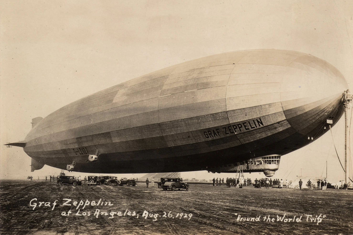
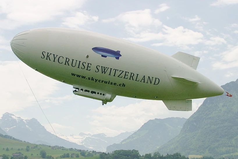
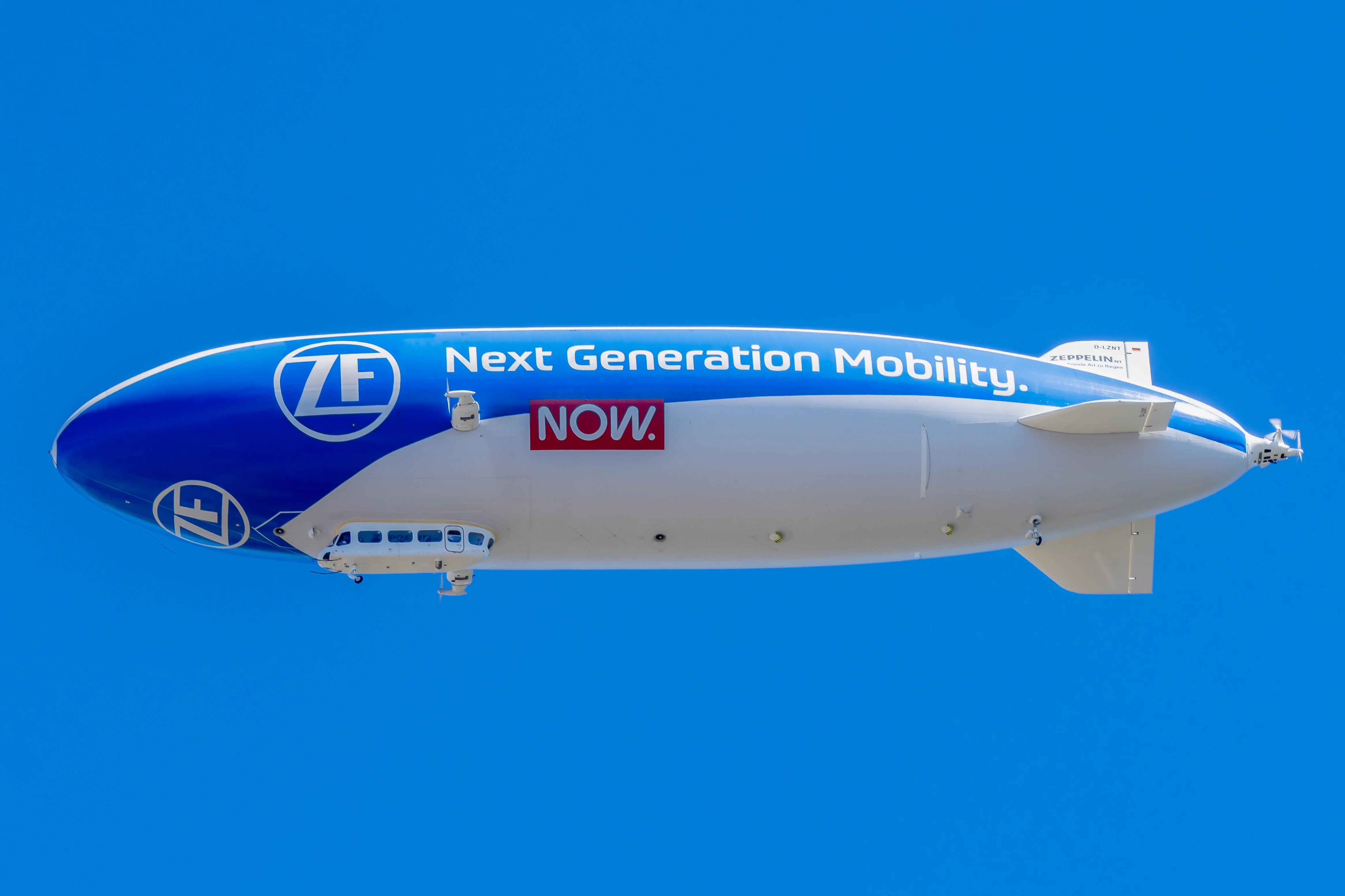
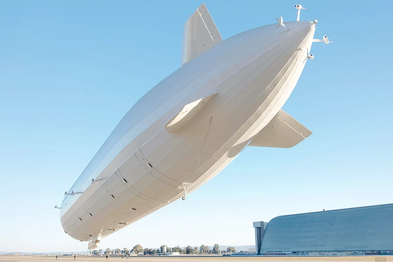
The number of large airship projects currently underway suggests that we are presently in such a period of renewed interest in airships, as described by Ardema (1977) almost half a century ago. Notably, LTA Research & Exploration LLC of the United States are flight-testing Pathfinder 1, a 124m long hybrid-electric rigid airship (Piesing, 2025); Flying Whales of France are developing the LCA60T, a hybrid-electric rigid airship with a payload capacity of 60 metric tonnes for aerial-crane applications (Cairns, 2023), and Hybrid Air Vehicles Ltd. of the United Kingdom are developing the Airlander 10, a kerosene-powered Hybrid Airship with a lift capacity of 10 metric tonnes for scheduled passenger transport operations, surveillance, cargo transport, and luxury tourism (Buckley, 2022; Ros, 2021).
This rekindling of interest in airships has been fuelled in particular by the focus on emissions reductions. The global aviation industry has agreed to try to achieve net-zero emissions by 2050 (ICAO, 2022). Due to their supposed superior energy efficiency, airships have been proposed as low carbon aeroplane alternatives for various air transport needs (Grundy & Bougon, 2022; Prentice & Knotts, 2016). However, this presumed energy efficiency advantage has to date not been appropriately quantified in the pertinent academic literature — see Sec. 2. This article aims to fill this gap by deriving mathematical relationships quantifying an airship’s energy efficiency in terms of key design parameters and comparing it with suitable equivalent relationships for aeroplanes. Furthermore, the compatibility of airships and aeroplanes with future low carbon energy carriers is evaluated.
2 Brief literature review
Academic interest in performance comparisons of airships and aeroplanes occurred in three phases, each about half a century apart.
Around the 1920s, following Alcock and Brown’s first non-stop transatlantic aeroplane crossing in June of 1919, and the R34’s non-stop airship flight from Scotland to New York[1][1]: This was the first direct flight from Europe to the United States (Alcock and Brown had flown from Newfoundland to Ireland), a feat that was not to be repeated by aeroplane for almost another eight years, until Lindbergh’s 1928 flight from New York to Paris in 1927. (carrying 31 passengers, two pigeons, and a kitten) just over two weeks later, the possibility of transatlantic passenger flights dawned on society, and aeronautical pundits debated whether the airship or the aeroplane would be employed for this undertaking (Blessing, 1928; d’Orcy, 1919; Fritsche, 1928; Parker, 1926). This debate necessarily involved comparative analyses of airship and aeroplane performance.
The consensus of the 1920s seemed to be that aeroplanes were unsuitable for long-distance travel, and that airships would dominate this use case. d’Orcy (1919) stated particularly confidently “[that] there cannot be the slightest doubt that the major, if not all, problems of aerial transport will in the near future be solved by the airship, and not by the airplane.” Airships were believed to have safety advantages, as they wouldn’t need to perform a forced landing in the case of engine failure, had much longer endurance in case weather conditions at the intended landing site were unsuitable, and engine repairs could be performed mid-flight (Blessing, 1928; d’Orcy, 1919; Fritsche, 1928; Parker, 1926). Comfort, in particular the lack of deafening engine noise and vibrations present in the early aeroplanes, were further cited as to the superiority of the airship (Blessing, 1928; d’Orcy, 1919; Fritsche, 1928; Parker, 1926). Authors did however concede that based on speed alone, the aeroplane should be preferred.[2][2]: It should be noted that the aeroplanes of the early 1920s did not generally exceed 260 km/h, which is just over twice as fast as an airships from the same era, as opposed to modern airliners, which are around seven times faster.
Authors also noted the superior range and payload capacity of airships compared to aeroplanes.[3] Fritsche (1928) pointed to the square-cube law, noting that “the useful or disposable load per hosepower of the airship increases very rapidly with volume, while in the airplane the useful load per horsepower is practically a constant, shows little increase with size, and actually decreases in extremely large sizes.” He further noted that, unlike the airship, the aeroplane does not increase in efficiency with size, and that for long ranges the fuel weight fraction is so great on an aeroplane that almost no payload can be carried, making economical operation impossible. An airship design’s range, on the other hand, can be increased simply by increasing its volume. Parker (1926) also notes that an airship’s efficiency increases with volume and decreases with speed, whereas the aeroplane’s does not. In a comparison of the effective lift-to-drag ratios of various airships with that of an aeroplane, he assumes for the aeroplane, a reminder of the aerodynamic improvements that have taken place in the past century.[4][4]: See Tbl. 2 for lift-to-drag ratios of modern aeroplanes. Parker (1926) notes that a small airship exhibits no energy efficiency advantage over an aeroplane at commercial speeds. Parker (1926) further presents a structural analysis demonstrating that an aeroplane’s empty weight ratio increases with gross weight (and range therefore decreases), whereas the opposite is true for an airship with a gross weight up to 150 tons. This analysis is based on a consideration of the respective weight fractions of components whose weights vary as , , and , where is the length scale. From this, it is concluded that airships and aeroplanes of the same lift capacity are unlikely to be in direct competition, as the aeroplane would dominate the small, and the airship the large sizes.
Blessing (1928) even went so far as to invent a non-sensical unit in an attempt to prove the inferiority of the aeroplanes of the times:
However, a crude analogy shows that no heavier-than-air machine can ever be developed that will exhibit the same relative propulsive power that a trained carrier pigeon produces. Assuming that a pigeon’s gross weight is two pounds and it flies at an average speed of forty miles an hour, there is derived a unit of twenty miles an hour a pound. Compare this with Lindbergh’s airplane which flew over midocean at an average speed of three one-hundredths of a mile a pound.
This quantity, speed per mass, is meaningless and obviously decreases as aircraft size increases. A more relevant quantity is specific power, or power per weight. Assuming equal lift-to-drag ratio, specific power is proportional to speed, and even Lindbergh’s Spirit of St. Louis exceeded a carrier pigeon’s specific power by approximately a factor of three.
In the 1970s, after the commencement of the Jet Age, the oil crisis prompted an interest in more efficient forms of transportation, including airships (Ardema, 1977; Marbury, 1975), however once oil prices decreased again, this interest dwindled. Marbury (1975) presents possibly the most comprehensive analysis of airship energy efficiency to date, and shows that the drag-to-weight ratio of an airship is proportional to , where is the airship’s length. From an analysis of drag-to-weight ratios of airships and aeroplanes it is concluded that airships under 2,000 tons displacement should limit their speed to between 80 and 120 knots. It is further noted that small airships are non-competitive with aeroplanes through higher fuel consumption.
As mentioned in Sec. 1, more recently the pressing issue of global heating has spurred a renewed interest in energy conservation and GHG emissions reductions, which has again fuelled an interest in the energy efficiency of airships. MacKay (2008, pp. 280–281) derives an expression for the energy used per unit distance[5][5]: This quantity is equivalent to the product of drag-to-lift ratio and gravitational acceleration. as a function of propulsion system efficiency, drag coefficient, speed, and airship length. To determine the energy efficiency of a hypothetical airship, numbers are substituted into the equation, from which it is concluded that an airship with a length of 400 m has comparable energy efficiency to a freight train. It is assumed in this analysis that an airship has a similar frontal area-referenced zero-lift drag coefficient as a Boeing 747. MacKay (2008), being a physicist by training rather than an aeronautical engineer, incorrectly uses a wing area-referenced drag coefficient here, so that the drag coefficient is too low by a factor of the ratio of wing area to frontal area, which is approximately 3. However, a Boeing 747’s frontal-area referenced drag coefficient is actually about 50% greater than that of an airship, so that the final drag coefficient estimate ends up too low only by a factor of about 2. Optimistic assumptions about the empty mass fraction are roughly balanced by pessimistic assumptions about propulsion system efficiency, so that the final energy consumption estimation ends up being too low by a factor of about 2 as well. It is also worth pointing out that the hypothetical airship evaluated here would have a volume of 870,000 m3, were it to be geometrically similar to the LZ-129. This is over 4 times larger in volume than the biggest airship ever built.
3 Defining efficiency
Despite this section’s title, the specific energy consumption of an aircraft is considered in this analysis instead of its reciprocal, the energy efficiency. Specific energy consumption is measured in energy units consumed per payload mass per distance[6][6]: For a comparison of the specific energy consumption of different modes of transport, see MacKay (2008, p. 128).. Expressions will be derived to evaluate the specific energy consumption as a function of an aircraft’s operational and design parameters.
Neglecting the influence of wind, the energy used per distance travelled can be rewritten in terms of the drag (or more generally resistance) and the overall efficiency of the propulsion system: (1) where is the overall propulsion system efficiency (the product of energy conversion or cycle efficiency and propulsive efficiency ). The specific energy consumption has units of . It can be non-dimensionalised through division by gravitational acceleration. The resulting expression can be rewritten in terms of a useful weight fraction and a drag-to-lift ratio , assuming steady, level flight: (2) This quantity shall be termed the specific payload resistance .
differs from the specific resistance defined by Gabrielli & Kármán (1950) in three aspects. Firstly, Gabrielli & Kármán (1950) considered the vehicle’s installed power rather than the power needed to sustain the vehicle’s velocity on a level trajectory. The installed power is usually greater than the power used during normal operation, e.g. to allow the vehicle to accelerate and climb. Secondly, the present analysis considers primary energy use, whereas Gabrielli & Kármán (1950) used the motor shaft power as the starting point. Thirdly, the payload weight is used here instead of the entire vehicle’s weight[7][7]: Gabrielli & Kármán (1950) expressed a desire for substituting the useful load for the gross weight, but decided not to do so due to lack of accessible data (Gabrielli & Kármán, 1950)..
Note that can be converted to kWh/tonne-km by multiplying by 2.725, or to kWh/(100 pax-km) by multiplying by 23, assuming a passenger mass of about 84 kg and a load factor of 100%[8][8]: This is of course an unrealistic assumption, however one that affects the airship and aeroplane approximately equally..
4 Energy efficiency of an airship
4.1 Basic formulation
We shall assume in our analysis that the airship is to remain approximately neutrally buoyant throughout flight. Where an airship is powered by a heavier-than-air fuel, measures need to be taken to prevent the airship’s static heaviness from decreasing as fuel is consumed. Historically, this has been achieved by a variety of means, including lifting gas venting, exhaust water recovery, rainwater collection, seawater pickup, or liquefaction/compression of air/lifting gas.
When neutrally buoyant and in steady, level flight, the lift is equal to the buoyant lift. Using Archimedes’ principle, the buoyant lift is evaluated as (3)where is the air density at the gas ceiling, and the standard air density at sea-level ().[9][9]: One may wonder why superheat does not appear as a parameter in Eqn. 3. This is because the superheat is inherent in the term , as superheat will cause the lifting gas to have a lower density. Eqn. 3 does not, however, account for superheat in the air contained in the hull. At large superheat and high ballonet fills this results in a buoyant lift prediction that is too low. Specifically for stratospheric airships during launch, the buoyant lift calculated via Eqn. 3 could be wildly inaccurate. Note that Eqn. 3 only holds if the only gases in the hull are lifting gas and air.[10][10]: If a fuel gas is carried in the hull such as Blaugas, Eqn. 3 can only be used if the effective fuel mass is multiplied by a factor , where is the fuel gas’s density. See A comparison of propulsion energy carriers for airships for more details.
The drag is simply the zero lift drag: (4)where is referenced to the hull volume[11][11]: More specifically, the usable hull volume, i.e. the hull volume that is occupied by lifting gas (as well as fuel gases) at the airship’s gas ceiling. to the power of two thirds, as is customary in airship aerodynamics.
Substituting Eqn. 3 and Eqn. 4 into Eqn. 2, we obtain (5) and are physical constants. is an operational parameter and is a function of outside air density, which can be varied by changing altitude, and airspeed, which is controlled by the engine power setting. Except for the payload weight fraction , all remaining parameters are design parameters. is a property of the airship’s aerodynamic design (and Reynolds number), is a characteristic of the propulsion system, depends on the choice of lifting gas, is given by the lifting gas fill, and is determined by the size of the airship.
Since the gross weight is the sum of empty weight , fuel weight , and payload weight, the payload weight fraction may be written as follows: (6)For a fuel-burning airship, the weight of the carried fuel decreases over time as it is burned. Since we are assuming constant heaviness, this mass must be replaced using one or several of the means mentioned previously. To avoid introducing an additional ballast weight term to Eqn. 6, we can simply define as the fuel weight at the start of the mission.
Since when neutrally buoyant and in steady, level flight, we can write the following for the empty weight fraction: (7)where is the empty mass fraction. By non-dimensionalising the empty mass with instead of the gross weight , becomes a measure of structural efficiency which is independent of the choice of lifting gas or chosen gas ceiling.[12][12]: This is not exactly true for a non-rigid (or semi-rigid) airship, since the ballonet fabric weight is a function of design gas ceiling. However, as the ballonet fabric weight is a relatively small fraction of total empty weight, this effect may be neglected. For a rigid airship, the gas cell fabric weight is independent of the gas ceiling.[13][13]: A similar parameter was used by Fulton (1934, 1934), who stated that for large rigid airships the “dead weight will amount to from 55 to 60 percent of the gross lift when filled with helium at sea level” (Fulton, 1934, p. 301). This measure of structural weight eliminates the dependence on the chosen gas ceiling, but not the dependence on lifting gas. It is worth noting that Fulton (1934)’s numbers are of little use today, due to the significant advances in materials and structures since (1934).
The fuel weight fraction in Eqn. 6 determines the airship’s range. Range is a more meaningful quantity than fuel weight fraction and enables direct comparison of airships and aeroplanes of various sizes powered by different energy carriers. Therefore, we will find an expression for to substitute into Eqn. 6, so that our final expression for is a function of range instead of fuel weight fraction.
The airship’s range is the product of velocity and the time it takes for its energy store to be spent,[14][14]: More accurately, this is the emergency range, as it does not include any fuel reserves. assuming constant velocity and again neglecting the influence of wind (the latter assumption will be relaxed in Sec. 4.4): (8) where is the energy carrier’s specific energy. Again setting , we have (9)
Substituting Eqn. 7 and Eqn. 9 into Eqn. 6, and subsequently Eqn. 6 into Eqn. 5, we have (10)
It is appropriate at this stage to consider the effect of the various parameters in Eqn. 10 on the airship’s specific payload resistance . It is self-evident that a lower drag coefficient and a higher energy conversion efficiency reduce the airship’s energy consumption. Furthermore, lowering the required range allows for less fuel to be carried, and therefore a higher payload weight fraction, reducing the energy consumed per payload mass and distance. Similarly, improving the airship’s structural efficiency (lower ) has the same effect. Moreover, choosing a lighter lifting gas (lower ) increases the buoyant lift for a given airship size and therefore improves efficiency. In addition, the airship’s design gas ceiling determines the value of and should be kept as low as possible to maximise efficiency. Lastly, should be minimised to maximise efficiency. This can be done by choosing the lowest practical airspeed and by flying as close to the airship’s gas ceiling as possible.[15][15]: In the presence of strong headwinds, it may be more efficient to fly at lower altitudes where the wind tends to be weaker due to the atmospheric boundary layer. More on this in Sec. 4.4.
Assuming that the airship flies at its gas ceiling for the duration of the journey, we can substitute for : (11)
We can see that is the reciprocal of a subtraction. The subtrahend, , must never exceed the minuend in magnitude, otherwise is undefined or negative. As the subtrahend approaches the minuend, approaches infinity. In practical terms, this corresponds to replacing more and more payload with fuel/battery weight, until the airship carries only fuel/batteries, and no more payload. Since no more payload is carried, the specific payload resistance is then infinite. Though of little practical relevance, this condition corresponds to the maximum theoretical range of the airship, and can be determined by equating the subtrahend and minuend and solving for : (12)
To allow plotting of Eqn. 11 against range without having to substitute scalar quantitites, we can rewrite Eqn. 11 using Eqn. 12 as follows: (13)A graph of Eqn. 13 is shown in Fig. 2. Note that as approaches , the specific payload resistance approaches , since the airship then carries no more payload, only fuel. Note that in practice the minimum achievable range is usually limited by structural considerations, which place an upper limit on the payload weight. Similarly, the maximum achievable range is limited by fuel tank size, and is usually significantly less than , which is a hypothetical value.
Finally, apart from the specific payload resistance, we are also interested in the amount of payload that a hypothetical airship design is able to carry at a given range. The payload mass is straightforwardly calculated from Eqn. 3, the definition of , Eqn. 8, and Eqn. 12: (14)
4.2 Estimating structural efficiency
Fig. 3 shows values of for various past and present airships. It can be seen that greater volume corresponds to a lower empty mass fraction, which is expected since the structural weights which scale with the square of the length scale (such as envelope fabric weight) contribute to a lesser extent at larger volumes. The use of composite materials is expected to reduce empty weight fractions considerably still.[16][16]: Pathfinder 1, the rigid structure of which is almost entirely made of CFRP and titanium, has a surprisingly high empty weight fraction. Perhaps this is due to battery mass.
4.3 Zero-lift drag coefficient
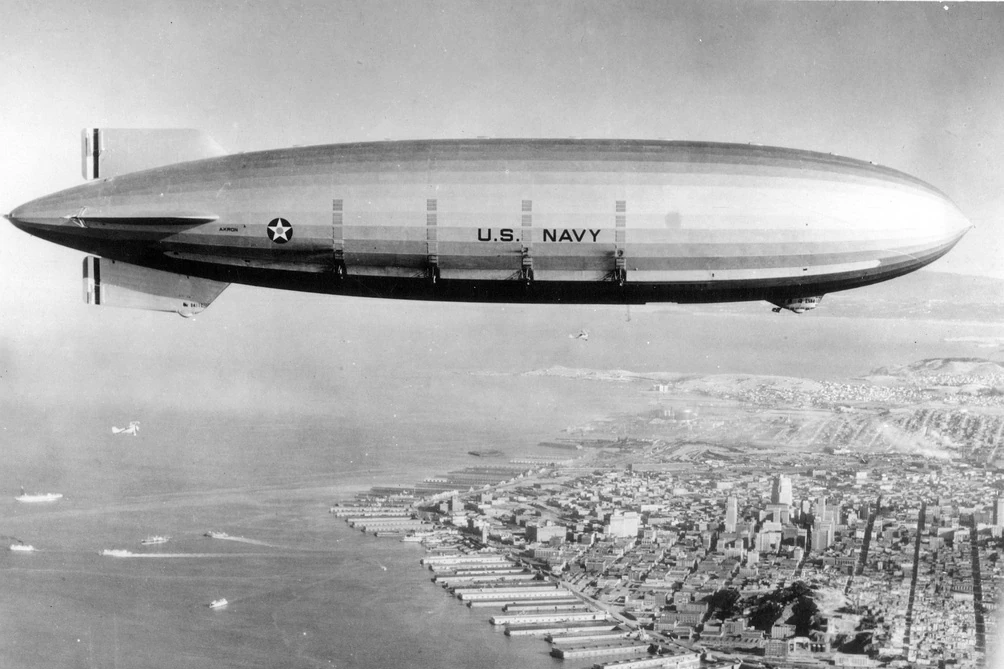
| USS Akron (ZRS-4) | 180,000 | 0.025 |
| ZP5K | 18,400 | 0.026 |
| LZ/126/USS Los Angeles (ZR-3) | 73,600 | 0.023 |
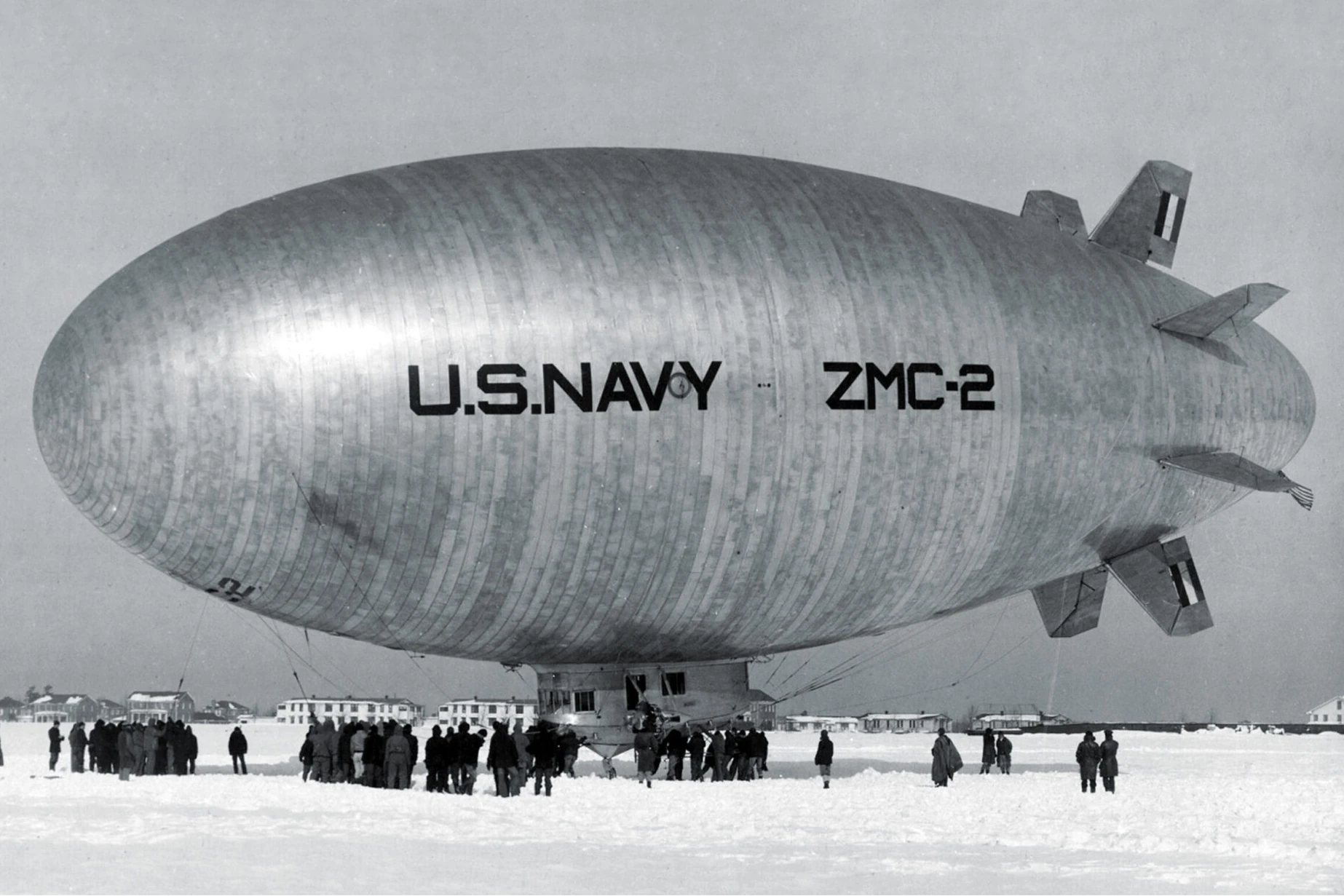
| Detroit ZMC-2 | 5,667 | 0.043 |
It is estimated that a modern airship design could achieve a drag coefficient of 0.020. Making use of distributed electric propulsion and/or boundary layer ingestion could lead to even lower drag.
4.4 The effect of wind
In the preceding analysis we neglected the effect of wind. Given an airship’s comparatively low airspeed, wind can have a significant impact on an airship’s energy consumption. To give some context, an airship travelling at an airspeed of 50 kts in a headwind of 25 kts uses eight times the energy it would use when covering the same distance at the same airspeed in calm wind conditions.
To see how we can adapt the derived equations to take account of wind, we will examine the range equation given in Eqn. 8. For the purpose of this analysis, we shall assume that the airship faces the same wind conditions all the way along its journey.
Consider the wind triangle in Fig. 5. is the ground speed, the wind speed, and the airspeed. is the angle between the ground speed and the wind speed vectors, and the crab angle. The in Eqn. 8 is really the distance covered in the airmass, not the distance covered on the ground. To make this distinction, we will use subscript for quantitites concerning the airmass, and subscript for ground values. Eqn. 8 then becomes (15)The distance covered in the airmass is greater than the ground distance by a factor . Similarly, we can define a ground speed based dynamic pressure . We then have . Substituting into Eqn. 15: (16)Now let . Then from Fig. 5, we have (17)[17]: Note that the term under the square root must be greater than zero. This condition corresponds to the ground speed needing to be positive.We can therefore see that if we replace with in all previous relationships, we obtain the equivalent relationships in the presence of wind.
We shall now consider what values of we might expect to find in practice. If , the airship’s energy consumption increases due to the presence of wind, if , it decreases. Continuing with our assumption that wind conditions are constant, we might argue wind presents a disadvantage for round trip journeys. Consider an airship travelling at 50 kts airspeed facing a 25 kts tailwind. We then have , i.e. a 70% energy saving compared to the no wind case. On the return leg, however, when the airship is subject to a 25 kts headwind, we have , i.e. a 700% increase in energy consumption. On average, we then have , i.e. a net increase in energy consumption of 630% with respect to the no wind case.
For short journeys, our assumption of constant wind conditions might be a valid one, but for longer routes this is no longer the case. The longer the journey, the greater the extent to which an airship can take advantage of the wind, by choosing a route that has the greatest possible tailwind components. The airship’s operational altitude must also be optimised along the journey, as wind conditions typically change as a function of altitude. Where such an optimisation is performed on longer routes, the presence of wind might actually turn out to be an advantage.
Regardless of the length of the journey, whether wind is an advantage or disadvantage on the whole can be determined by a Monte Carlo analysis of algorithmically optimised routes. This analysis could yield an average value of , which can subsequently be used to determine . That value of is a function of climate, maximum airspeed, maximum operational altitude, and a variety of other parameters. As such an analysis falls outside the scope of the present work, we assume for simplicity in what follows.
5 Energy efficiency of an aeroplane
For aeroplanes, Eqns. 2 and 6 still hold. We therefore have (18)
Note that we are neglecting the energy required for initial climb in this analysis. While a neutrally buoyant airship does not require any additional energy to climb, this is of course not the case for heavier-than-air craft. For short-haul flights, the fuel required for climb makes up a significant proportion of the total energy consumption and is anything but negligible. However, we must remind ourselves of the reasons why aeroplanes fly at high altitudes. The lower air density allows for greater speeds, and flying above the clouds increases passenger comfort due to reduced turbulence. However, this comes at the cost of the fuel required for initial climb. If greater focus was placed on efficiency, aeroplanes for regional operations might be designed to cruise at lower altitudes. It must furthermore be noted that airships cannot fly at the cruising altitudes of jet aeroplanes[18][18]: Or if they did wouldn’t carry any meaningful payload., and it therefore seems like a fairer comparison to not include the energy required for initial climb.
Next, we need to eliminate the fuel weight fraction in Eqn. 18 by substituting a function of the aeroplane’s range for it.
At this point, we must distinguish between fuel-burning and battery-powered aeroplanes. This is because fuel-burning aeroplanes become lighter as they burn fuel, and battery-powered aeroplanes don’t. Unlike an airship, an aeroplane suffers from induced drag, and therefore uses more energy the heavier it is. The fuel-burning aeroplane thus becomes more efficient as it burns off fuel, whereas the battery-powered aeroplane does not.[19][19]: For airships, we didn’t have to make this distinction, because we assumed that the airship remained neutrally buoyant during flight. As mentioned, in the case of a fuel-burning airship, this necessitates the implementation of a heaviness-conservation mechanism such as exhaust water recovery. A battery-powered airship needs no such mechanism.
5.1 Fuel-burning aeroplane
A fuel-burning aeroplane need not maintain constant heaviness, and becomes lighter as it burns fuel. A fuel-burning aeroplane’s range is given by the Breguet range equation, which is written here in terms of an overall propulsion system efficiency rather than a thrust specific fuel consumption: (19)Solving for yields (20) Substituting Eqn. 20 into Eqn. 18, we have (21)Note that in practice there is a lower limit on , which is set by the MZFW, and an upper limit, which is determined by the fuel tank capacity.
As before, the hypothetical maximum range can be found by equating the subtraction in brackets to zero: (22)The same result may be obtained by setting and substituting Eqn. 6 into Eqn. 19.
Lastly, as for the airship, we are going to derive an expression for , as we did for the airship. While this equation is not very informative on its own, it is useful for plotting in Sec. 6, as it enables straightforward calculation of from once has already been calculated: (23)
The payload weight fraction can then be expressed as (24)
5.2 Battery-electric aeroplane
A battery-powered aeroplane’s weight doesn’t change as the battery is exhausted. This simplifies the equations somewhat: (25)[20]: Note that the “” subscript in and should probably be replaced with a “” for a battery powered aeroplane, however we shall stick to the “” for consistency. For a battery powered aeroplane, is the battery’s specific energy, and the battery’s weight.For we have: (26)The hypothetical maximum range can be found by substituting for the fuel weight fraction in Eqn. 25: (27) Lastly, we can again derive an expression for . As it turns out, this is the exact same expression as for the airship! The only difference is in how is calculated: (28)
For completeness and later plotting, the payload weight fraction is given as (29)Note the parallels to the expression for the airship ( Eqn. 14 ).
5.3 Values of , , , and
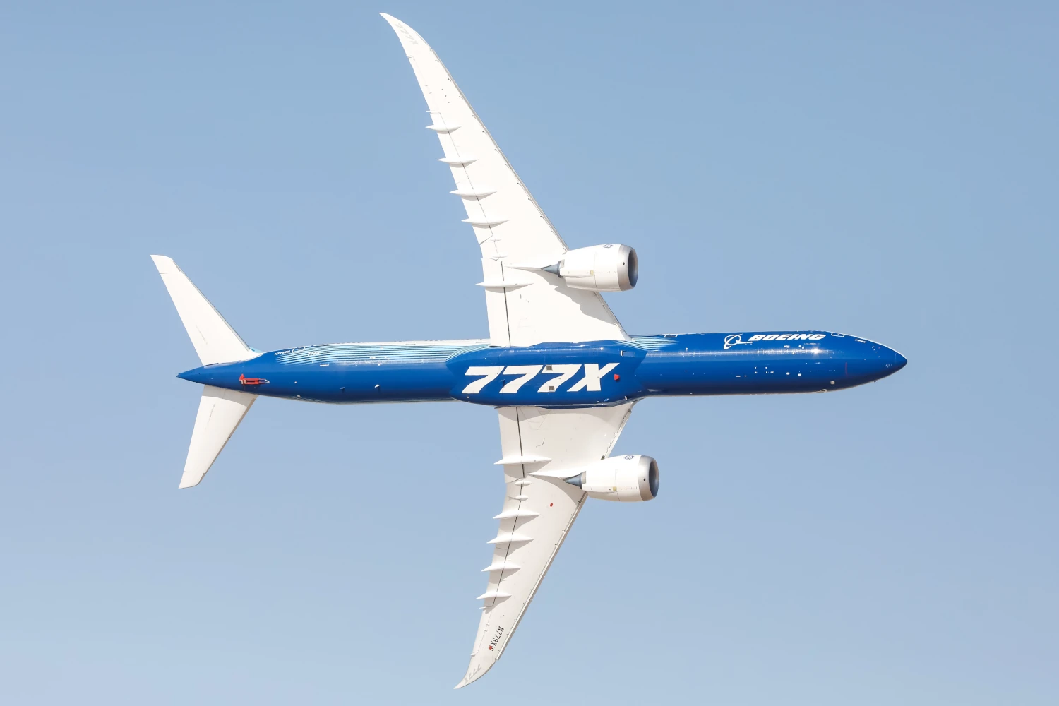
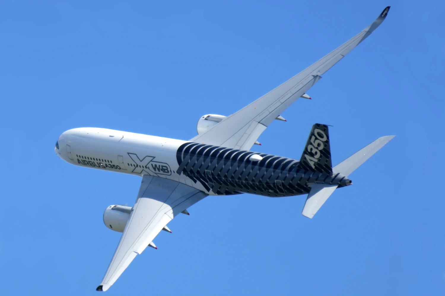
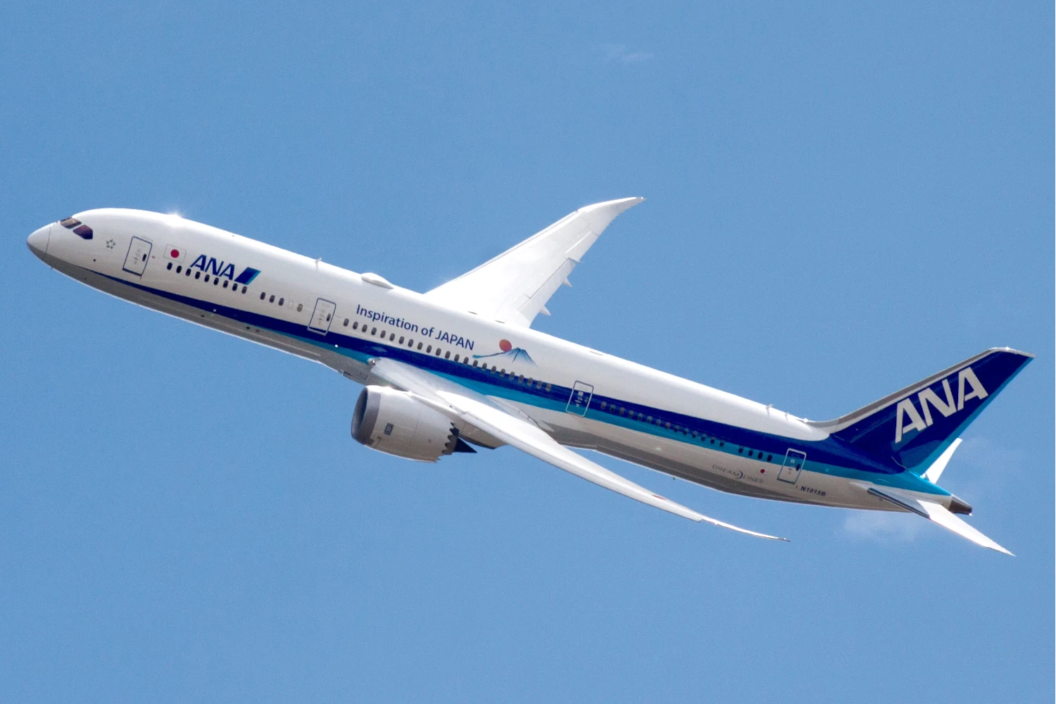
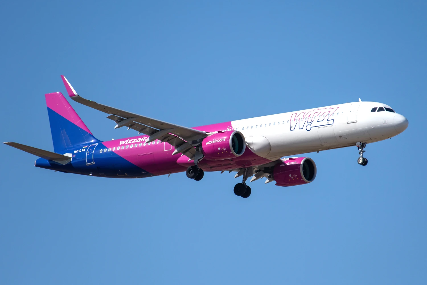
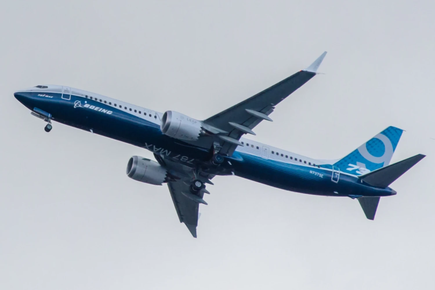
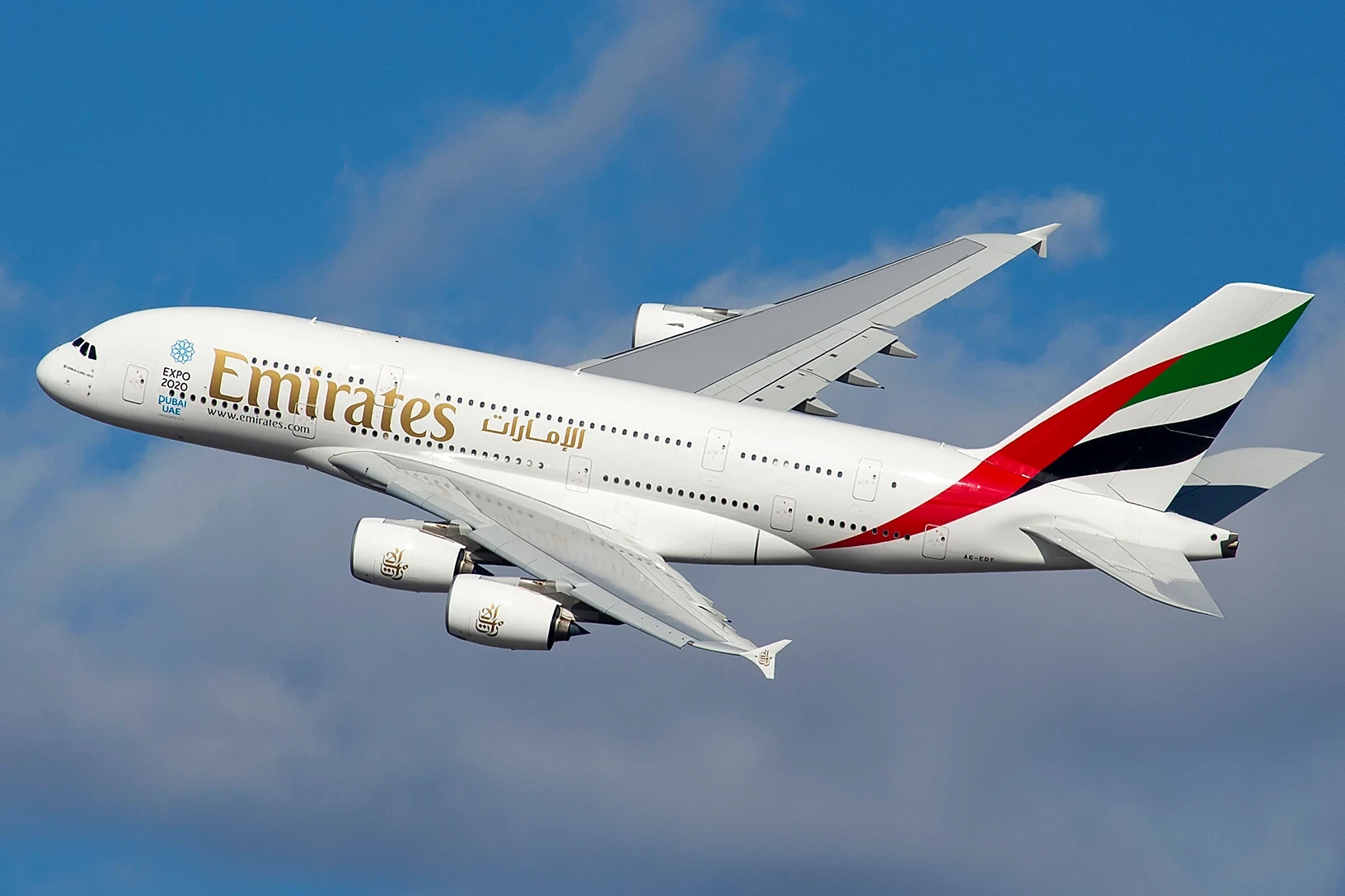
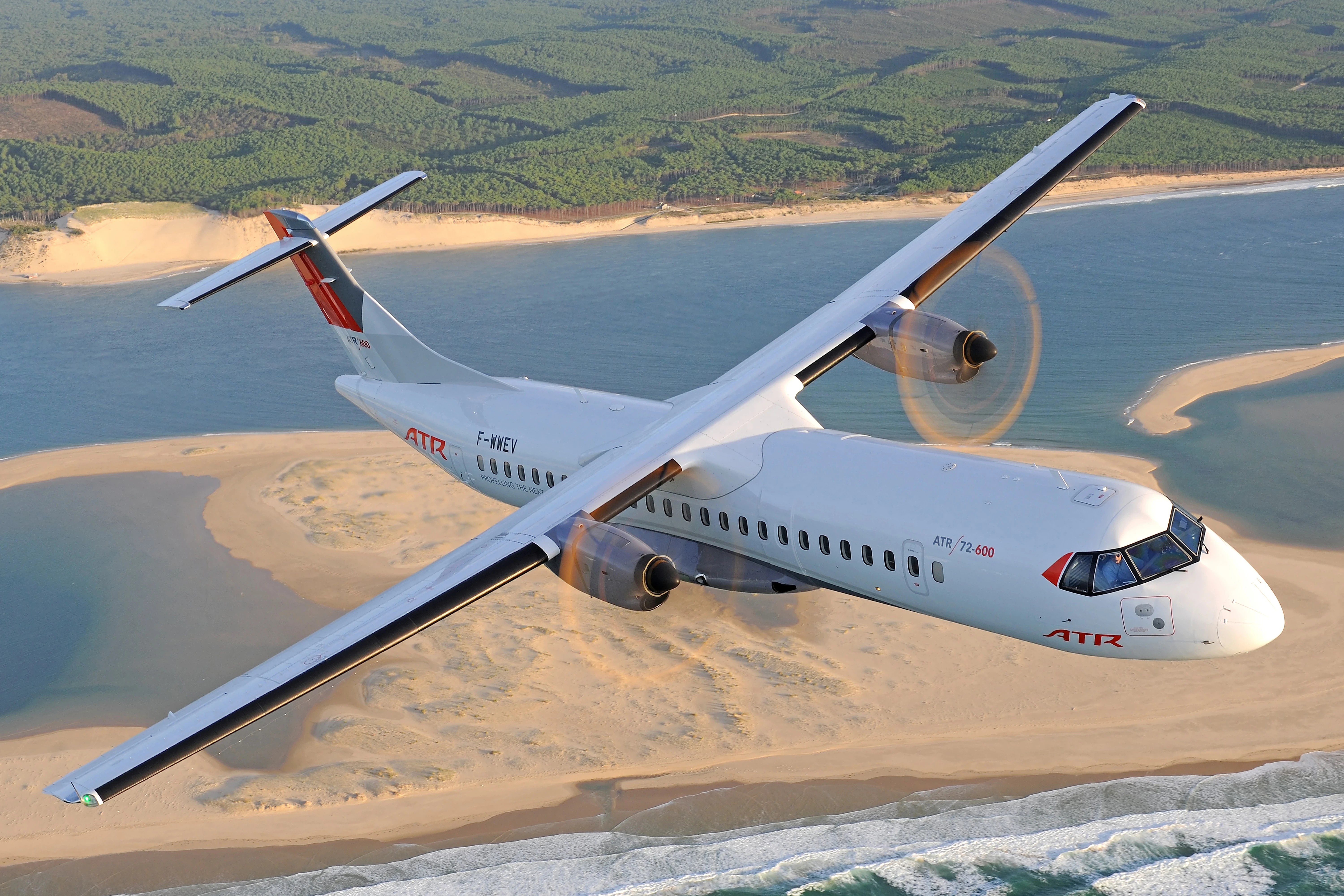
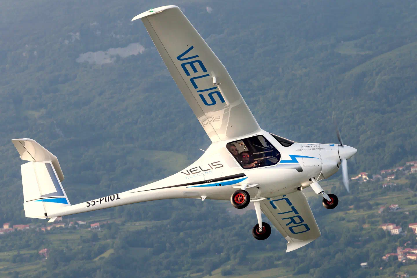
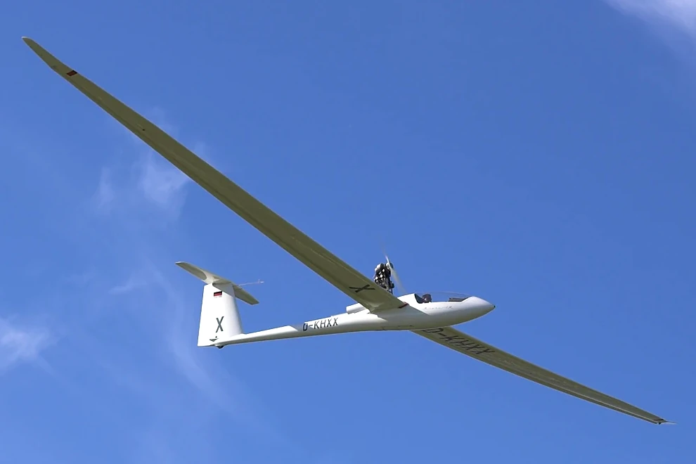
Tbl. 2 contains key performance parameters of the aeroplanes shown in Fig. 6.
|
|
||||
|---|---|---|---|---|
| Boeing 777X-9 (GE90-110B/-115B) |
0.42 | 21 | 0.43 | 11.9 |
| Airbus A350-941 (Rolls-Royce Trent XWB-84) |
0.41 | 20 | 0.43 | 11.9 |
| Boeing 787-9 Dreamliner (GEnx-1B or RR Trent 1000) |
0.51 | 20 | 0.41 | 11.9 |
| Airbus A321neo (CFM LEAP-1A32) |
0.51 | 17 | 0.36 | 11.9 |
| Boeing 737 MAX 9 (CFM LEAP-1B28B1) |
0.54 | 17 | 0.36 | 11.9 |
| Airbus A380-842 (Rolls-Royce Trent 972) |
0.45 | 18 | 0.37 | 11.9 |
| ATR 72-600 (PW127M) |
0.57 | 17 | [21]0.20 | 11.9 |
| Pipistrel Velis Electro (Pipistrel E-811-268MVLC) |
[22]0.49 | 15 | 0.90 | 0.16 |
| Schempp-Hirth Nimbus-4DM (Rotax 535C) |
0.73 | 60 | 0.18 | 12.2 |
[21]: Due to lack of engine data, for the ATR 72 was estimated from fuel consumption at cruise, cruise speed, and the lift-to-drag ratio.
[22]: Empty weight excluding battery weight.
6 Airship vs aeroplane
We can now compare the specific payload resistance of airships and aeroplanes. A few observations can be made from the derived expressions. Firstly, it is noteworthy that from Eqn. 11 an airship’s specific payload resistance is anti-proportional to , i.e. specific resistance decreases with increasing gravitational acceleration. In the equivalent expressions for aeroplanes however, is absent. This suggests that an airship is using gravity to its advantage, whereas an aeroplane is not. It can furthermore be concluded, as other authors have, that an airship’s specific energy consumption can be decreased by increasing volume, and its range increased. An aeroplane’s energy consumption and range, however, are size-independent.[23][23]: This prompted authors in the 1920s to conclude that aeroplanes were not suited for transatlantic travel, whereas airships were.
Fig. 8 is an interactive graph enabling an airship design and an aeroplane design to be compared in terms of their specific payload resistances, plotted against range . The sliders allow changing of all relevant parameters, with the graph being updated automatically. Note that the ranges do not include any reserves.
The default parameter values aim to compare a hypothetical modern airship design with an equally hypothetical efficient aeroplane design. For both the airship and aeroplane, is set to , which appears to be the limit of current thermal engine technology. Similarly, is set to the value for kerosene in both cases. The airship’s empty mass fraction is set to , a value which should be practically achievable with modern materials. The aeroplane’s empty weight fraction is set to , the current best-in-class value for airliners. The airship’s drag coefficient is set to , which should be achievable with a carefully designed aerodynamic shape. The aeroplane’s lift-to-drag ratio is set at , a value which an aeroplane with a truss-braced non-swept high aspect ratio wing such as the Boeing SUGAR Volt concept might achieve. The airship’s gas volume is somewhat arbitrarily set at m3, the same gas volume as that of the LZ-127. Speed is set at km/h or 60 kts, a value that might enable both freight transport as well as short-haul passenger transport. Lastly, the value of corresponds to the use of pure Helium, and to a gas ceiling of 5,000 ft at ISA conditions.
In addition to the specific payload resistance, Fig. 8 also shows the airship’s payload mass against range . In the case of the aeroplane, it makes no sense to plot the payload mass, as it is dependent on the aeroplane’s size, and the size has no bearing on its efficiency. Rather than introduce another slider for the aeroplane’s size, we instead plot the payload weight fraction against range.
As can be seen, the specific payload resistances of the hypothetical airship and aeroplane are very similar. This analysis suggests that the airship’s energy efficiency advantage is not as striking as some claim.
It is further noteworthy, that a fuel-powered aeroplane has an advantage over the airship at larger ranges. As fuel is burnt, the aeroplane becomes lighter and thus more efficient, whereas the airship’s efficiency is unaffected by fuel burn. The battery-powered aeroplane, however, exhibits no such advantage.
7 Future energy carriers
Decarbonising air transport requires not only efficiency improvements, but also the adoption of renewable energy carriers such as SAF, hydrogen, or batteries. Since the global SAF supply is limited by the availability of used cooking oil, fuel crops, or other biomass sources, the focus is placed here on batteries and hydrogen. As it turns out, both are much better suited for use with airships than aeroplanes.
Batteries don’t change their mass as they are exhausted. This is a disadvantage in the case of aeroplanes, and leads to a significant range reduction compared to a hypothetical battery whose weight is proportional to its remaining capacity. In the case of the airship, however, this is an advantage, as static heaviness needs to be kept constant throughout flight. Consequently, no heaviness conservation mechanism such as an exhaust water recovery apparatus is needed, leading to reduced empty mass.
Battery-powered aircraft also have low range due to the vastly lower specific energy of batteries compared to hydrocarbons. A battery-powered airship’s range can be increased by increasing the airship’s volume, whereas the size of a battery-powered aeroplane has no influence on its range.[24][24]: Provided is not a function of size.
To use hydrogen on aeroplanes, it needs to be either liquefied or compressed to very high pressures. Both liquefaction and compression are energy intensive, with liquefaction consuming as much as 35% of the energy contained in the hydrogen being liquefied. This considerably increases operating costs. In the case of compressed hydrogen, heavy high pressure tanks are needed for containment. The mass of these tanks exceeds the mass of contained hydrogen by a factor of 16, considerably reducing the effective specific energy. Even when liquefied or compressed, hydrogen’s volumetric energy density is still so low that very large tanks are needed, leading to the displacement of passengers or cargo.
In an airship however, available volume is not scarce, and irrespective of whether hydrogen is stored in liquid of compressed form, no payload is displaced. On an airship, hydrogen can also be stored uncompressed in gaseous form, in fuel ballonets. The lack of compression enables considerable upfront energy and thus operating cost savings. Since static heaviness increases as hydrogen is oxidised, ballast water needs to be carried and dropped at the same time as fuel is spent. The continuous heaviness adjustments can also be used to compensate for superheat, leading to superior aerodynamic efficiency, as no dynamic lift and thus no induced drag needs to be generated.
8 Conclusions
The airship’s presumed efficiency advantage is not as significant as many claim. This, of course, depends on a variety of design and operational parameters, in particular the volume and speed , where larger volume and lower speed lead to higher efficiency.
At longer ranges the aeroplane becomes more efficient, as it becomes lighter as fuel is burned, and therefore the effective payload weight fraction increases. The airship exhibits no such advantage, as its heaviness must remain constant throughout flight.
The airship is much better suited for the use of renewable energy carriers such as hydrogen or batteries than the aeroplane due to plentiful available volume and favourable scaling laws.
Particularly promising seems the use of uncompressed, gaseos hydrogen as a cheap, renewable energy carrier with comparatively high specific energy in airships. This energy carrier cannot be used on aeroplanes due to lack of volume. An airship powered in this way could serve as a zero-carbon alternative for many current air transport needs.