A Comparison of Propulsion Energy Carriers for Airships
And Their Suitability for Future Zero Carbon Airships
Published 15/01/2025, last edited 05/09/2025
Contents
1 Introduction
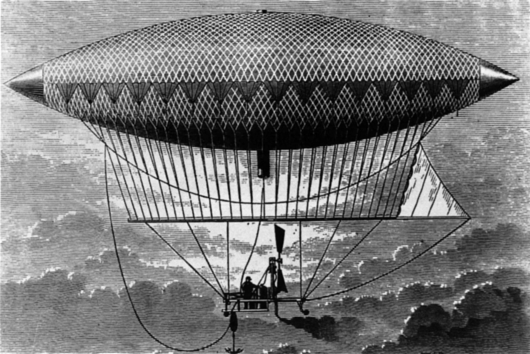
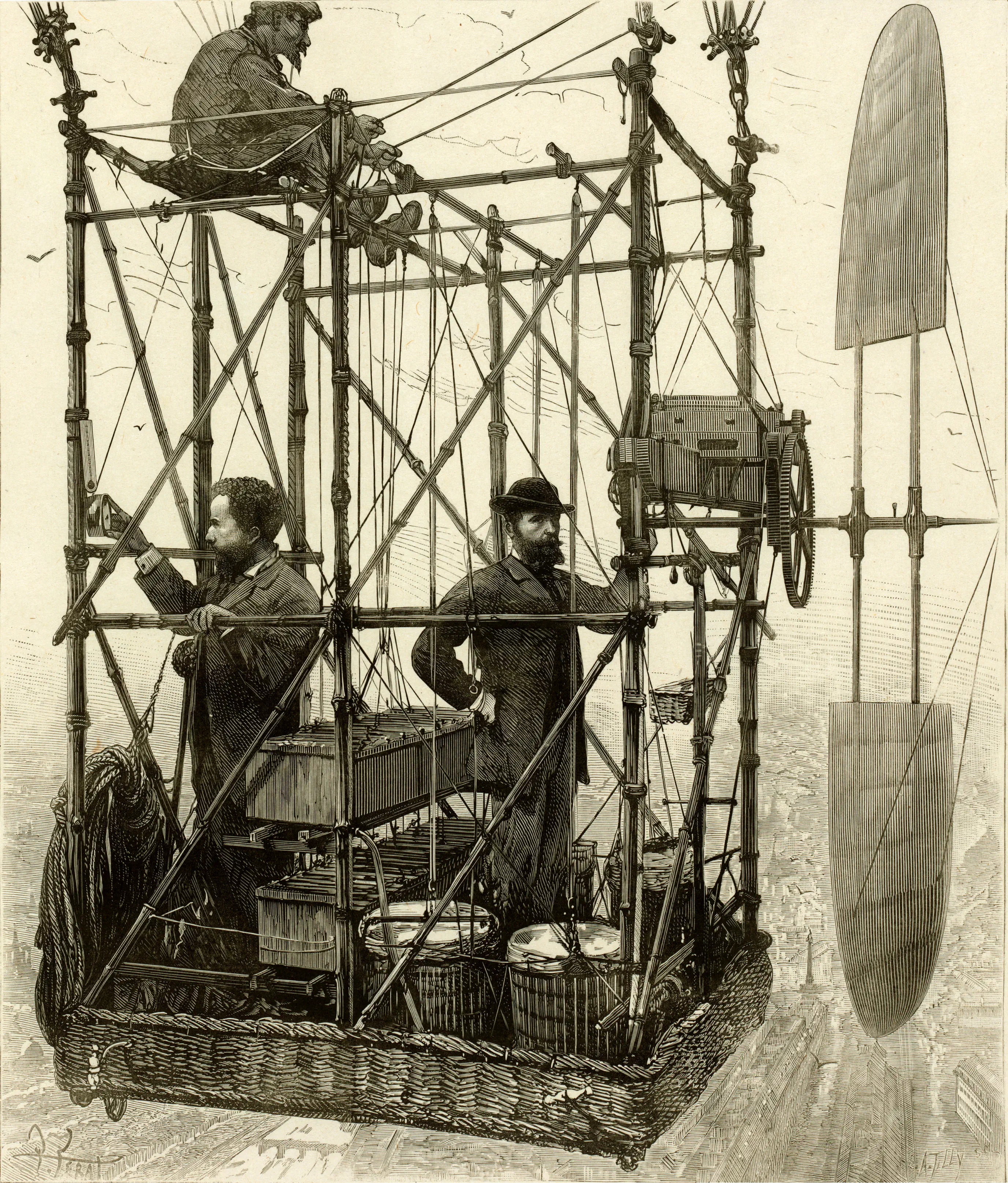
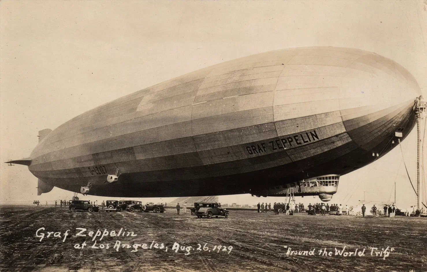
Various propulsion energy carriers have been used for airships ever since Henri Giffard performed the world’s first powered flight in his coke[1][1]: Coke is produced by baking coal at high temperatures in the absence of oxygen, which removes impurities and effectively produces pure carbon. fuelled, steam engine powered airship, the Giffard dirigible[2]. 31 years later, in 1883, the Tissandier brothers flew the world’s first battery powered electric airship.[3] Almost 46 years later, in 1929, the LZ 127 Graf Zeppelin[4] carried over three dozen passengers and crew members around the world, fuelled by Blau gas[5][5]: Blau gas is produced by decomposing mineral oils with heat, and has approximately the same density as air. and petrol.
In more recent times, airships have been suggested as a lower or zero carbon alternative to aeroplanes for some air transport applications, due to their supposed superior energy efficiency. However, the carbon emitted by an airship depends not just on the airship’s energy efficiency, but also on the choice of energy carrier. The suitability of an energy carrier for airships depends on a number of different factors, including its gravimetric energy density, the efficiency of the employed energy conversion process, as well as the carrier’s volumetric mass density relative to that of air. In the following, a comparison of both past as well as potential future airship propulsion energy carriers is presented, and their suitability for future zero carbon airships is evaluated.
2 Abbreviations and symbols
| Abbreviation | Meaning |
|---|---|
| CFRP | Carbon-fibre reinforced plastic |
| CHP | Combined heat and power |
| GWP | Global warming potential |
| HHV | Higher heating value |
| ISA | International Standard Atmosphere |
| LHV | Lower heating value |
| RED | Raikhlin Aircraft Engine Developments GmbH |
| SFC | Specific fuel consumption |
| Symbol | Meaning |
|---|---|
| Specific propulsive energy | |
| Shaft work | |
| Mass of energy carrier (fuel or battery) | |
| Chemical energy conversion efficiency (cycle efficiency, or powertrain efficiency on electric aircraft) | |
| Specific chemical energy | |
| Buoyant lift force | |
| Density of air | |
| Lifting gas density | |
| Outside air density at sea level, assuming ISA conditions () | |
| Outside air density at pressure altitude, where a non-rigid airship’s ballonets are empty and a rigid airship’s gas bags are full | |
| Hull volume | |
| Gravitational acceleration (9.81 ms-2) | |
| Fuel volume | |
| Fuel density |
3 Basic principles and assumptions
An airship designer may choose from a variety of propulsion energy carriers, some of which have already been mentioned in the introduction. The choice of energy carrier must lead to a propulsion system design which can meet range/endurance requirements while staying within weight budget. Furthermore, modern airship designers must also take into account the environmental impact of the chosen energy carrier. To evaluate the performance of an energy carrier, its specific propulsive energy will be determined, which will be defined in Sec. 3.1. To determine the environmental impact of a fuel, its in-flight carbon dioxide emissions will be determined, but this will not be the only consideration.
Amonst the energy carriers under consideration there are fuels and batteries. Among the fuels, some are are heavier than air (e.g. diesel), and others ligher than air (e.g. uncompressed gaseous hydrogen). We shall assume in our analysis that the airship is to remain approximately neutrally buoyant throughout flight.
For heavier-than-air fuels, this means measures need to be taken to prevent the airship’s static heaviness from decreasing as fuel is consumed. Historically, this has been achieved by a variety of means:
- lifting gas venting,
- exhaust water recovery,
- rainwater collection,
- seawater pickup, or
- liquefaction/compression of air/lifting gas.
Since lifting gas venting is prohibitively costly when using Helium, rainwater collection isn’t possible in the absence of rain, seawater pickup isn’t possible in the absence of sea, and liquefaction/compression of air/lifting gas adds a lot of weight to the airship, we shall focus here on exhaust water recovery.
Conversely, in case of a lighter-than-air fuel like uncompressed gaseous hydrogen, ballast needs to be carried and slowly dropped as fuel is consumed to maintain constant static heaviness. This means that the extra lift created by a lighter-than-air fuel cannot be used and must be squandered with ballast.[6][6]: For passenger carrying airships, some of the reduction in buoyancy caused by fuel consumption could be compensated by the in-flight dropping of greywater, so that not all of the lifting gas’s buoyancy is wasted.
Batteries don’t change their mass as they are depleted and therefore no heaviness compensation measures need to be taken.
3.1 Evaluation of specific propulsive energy
The specific propulsive energy of an energy carrier will be calculated here as the quotient of generated shaft work and energy carrier mass [7][7]: In case of a pressurised fuel, where the fuel tank mass is a constant proportion of the fuel mass, the tank weight will be included in as well. See Sec. 4.4.. This means that the specific propulsive energy is also a function of the chemical energy conversion efficiency : (1)where is the energy carrier’s specific chemical energy (LHV or HHV in the case of fuels, depending on which of LHV or HHV was used to calculate ).
At this point we must think about how this quantity may be used by an airship designer to inform their choice of energy carrier. A conceptual designer might start with an initial estimate of hull volume and a choice of lifting gas. Along with a choice of pressure altitude and a consideration of expected atmospheric conditions, this hull volume and lifting gas can then be used to calculate buoyant lift using Archimedes’ principle, as (2)where is the ratio of lifting gas density to outside air density, and is the ratio of outside air density at pressure altitude to standard sea level air density.[8][8]: One may wonder why superheat does not appear as a parameter in Eqn. 2. This is because the superheat is inherent in the term , as superheat will cause the lifting gas to have a lower density. Eqn. 2 does not, however, account for superheat in the air contained in the hull. At large superheat and high ballonet fills this results in a buoyant lift prediction that is too low. Specifically for stratospheric airships during launch, the buoyant lift calculated via Eqn. 2 could be wildly inaccurate. Eqn. 2 holds if the only gases in the hull are lifting gas and air. After obtaining a number for the buoyant lift, the airship designer may use an estimate of drag coefficient along with the hull volume, required cruise speed, and required range to calculate the required propulsive energy which the airship needs to carry at the start of the mission. This propuslive energy can then be converted to shaft work via the propeller efficiency, according to . Lastly, the total mass of the propulsion system including energy storage can be calculated according to (3)where represents the masses of all the components comprising the propulsion system apart from energy storage, such as tanks (if not already included in , as in the case of compressed fuels), fuel lines, engines, or mass of conductors, inverters, and electric motors in the case of electric propulsion. After has been evaluated for all considered energy carriers, the lightest solution may be chosen.
A slight difficulty arises when the fuel under consideration is gaseous. In that case, Eqn. 2 is no longer valid. However, as we will show in the following paragraph, Eqn. 2 may still be used if we scale the value of of the gaseous fuel by a factor of . This greatly simplifies our evaluation of different energy carriers, as we no longer need to worry about whether a fuel is gaseous or not.
Consider Fig. 4(a) and Fig. 4(b). If we calculate buoyant lift less fuel weight according to (4)then we obtain the correct result for Fig. 4(a), but not for Fig. 4(b). In the case of Fig. 4(b), the right-hand side of Eqn. 4 is too large by a an amount equal to the difference of lifting gas fills in Fig. 4(a) and Fig. 4(b). We can correct this by subtracting this lifting gas fill: (5)We can think of as the mass which the fuel would have if it had no volume, and its volume was instead occupied by lifting gas. Consequently, if we replace in Eqn. 1 with , we can continue to use Eqn. 2 and Eqn. 3 to compare our energy carrier options. We then have (6)
For a gaseous fuel with a density less than air, additional ballast needs to be taken and released at the same time as fuel is burned to maintain constant static heaviness. This reduces the effective specific propulsive energy: (7)where is the mass of the additional ballast. The ballast mass must be equal to the buoyant lift of the ligher-than-air fuel, so that the static heaviness doesn’t change once all the fuel is used up and its volume reduction has been compensated for by additional air ballonet fill: (8)Substitution yields (9)
In summary, (10)We can observe how differs from for different fuel densities by plotting the quotient :
Another possible configuration of which examples will be presented in Sec. 4 is a dual fuel propulsion system, whereby a lighter-than-air gaseous fuel is used in combination with a heavier-than-air liquid fuel, and both fuels are burned in such a ratio that static heaviness remains constant. This configuration is shown in Fig. 6.
To avoid having to take ballast water or having to recover water from the exhaust, the fuel mixture must have the same combined density as air, where is the mass of gaseous fuel, the mass of liquid fuel, and the volume of gaseous fuel: (11)which may be rearranged to (12)The specific propulsive energy is then evaluated, where the subscripts have the same meaning as in the previous equation: (13)where the last expression is obtained by substituting Eqn. 12.
3.2 Environmental impact
To evaluate the environmental impact of an airship fuel, we shall consider its carbon dioxide emissions rather than its global warming potential (GWP). Evaluating the GWP requires consideration of a specific timespan (e.g. the 50– or 100–year GWP) as well as assumptions about the impact of non- emissions such as water vapour[9][9]: An airship emits water vapour at much lower altitudes, thereby greatly reducing the propability of subsequent cloud formation, so the impact is not comparable to that of jet aeroplanes., which would complicate the task. Similarly, to simplify the task further, we shall consider the in-flight carbon dioxide emissions of a fuel, and not the indirect emissions created during fuel production and transport, even though these indirect emissions are often substantial. An exception to this rule will be biogas, where the lifecycle emissions are considered as well.[10][10]: As we shall see, biogas emits a rather substantial amount of carbon dioxide in flight, however all of that carbon dioxide was previously captured from the air, making it a sustainable fuel.
Carbon dioxide emissions are stated in kg of per kWh of produced shaft power. This is calculated as follows: (14)For mixtures of two fuels, emissions are calculated as (15)where the subscripts and refer to the two fuels, and (16)
4 Propulsion energy carriers
4.1 Diesel/kerosene and petrol/Avgas
Jet A-1 jet fuel and Avgas 100LL have heats of combustion of kWh/kg and kWh/kg respectively. The RED A03 aircraft diesel engine, which shall be used here as a representative example, has a minimum SFC of g/kWh (Raikhlin Aircraft Engine Developments GmbH, 2012), which corresponds to a thermodynamic efficiency of %. For our representative petrol/Avgas engine, we shall use the Lycoming IO-360-C1G6, the engine in use on the Zeppelin NT-07 (European Aviation Safety Agency, 2008). This engine has a minimum specific fuel consumption of lb/hp-hr (Lycoming, 2005, p. 3-20), which corresponds to a thermodynamic efficiency of %. Specific propulsive energies are calculated using Eqn. 1 as and kWh/kg for diesel/kerosene and petrol/Avgas respectively.
Note that both diesel and petrol require an exhaust water recovery system to maintain constant heaviness. For diesel, the chemical formula may be used. Therefore, its oxidation is described by Similarly, if we assume that octane () is representative of petrol/Avgas, we have for its oxidation Therefore, in the combustion of diesel and petrol, approximately 29% and 42% more water than combusted fuel by weight is produced during oxidation, respectively. This means that an exhaust gas condenser need not extract all of the water from the exhaust in order to maintain constant static heaviness. It should be noted that exhaust gas condensers have historically suffered from corrosion issues.
Carbon dioxide emissions of diesel and petrol may be derived from the oxidation equations and amount to and kg /kg fuel, which corresponds to and kg /kWh shaft work respectively, according to Eqn. 14.
4.2 Blau gas
Blau gas is a mixture of 39% alkanes by volume (mainly methane and ethane) and 61% alkenes (ethylene, butylene, acetylene, and around 33% heavier hydrocarbons, by total volume, whose partial pressures are low enough for these constituents to be gaseous), and has a density that of air (Teed, 1931). It is manufactured by decomposing mineral oils with heat, scrubbing the resulting gas with water to remove carbon, purifying it to remove carbon dioxide, compressing it to 100 atmospheres, and drawing off the remaining gas (methane and hydrogen). The resulting liquid gasifies completely when expanded to atmospheric pressure.
Blau gas, due to its auto-ignition temperature, requires an engine with a compression ratio no higher than 9:1 (Teed, 1931). As far as I know, there are no current aircraft engines that can run on Blau gas, and so we shall assume that our hypothetical Blau gas engine has the same thermodynamic efficiency as the Lycoming IO-360 (%), which has a compression ratio of 8.5:1, lower than the highest useful compression ratio of Blau gas. The Blau gas could be contained in a fuel ballonet in the case of a non-rigid airship, or a fuel gas bag in case of a rigid airship. For the purposes of calculating specific propulsive energy as well as carbon dioxide emissions, the heat of combustion of Blau gas is assumed identical to that of ethane ( kWh/kg), a gas of chemical formula with approximately the same density as air. According to Eqn. 10, we calculate a specific propuslive energy of kWh/kg.
The combustion of ethane is described by the chemical equation from which we calculate carbon dioxide emissions of kg /kg fuel, corresponding to kg /kWh shaft work as per Eqn. 14.
4.3 Biogas
To my knowledge, biogas has not previously been proposed as an airship fuel.[11][11]: As it turns out, Johannes Eißing briefly suggested the use of biogas as an airship fuel in a lecture he gave as part of the Hamburg Aerospace Lecture Series (Eißing, 2020), though without providing further details. Biogas is produced via anaerobic digestion of feedstocks such as agricultural waste, green waste, wastewater, and manure. It consists primarily of methane, carbon dioxide, small amounts of hydrogen sulfide, and water vapour. Biogas must go through a cleaning process to remove the highly corrosive hydrogen sulfide. Afterwards, it can be burned in CHP gas engines, or further upgraded to biomethane. The percentage of methane by volume varies between 50–80%, the majority of the remainder being carbon dioxide.
A gas of equal parts methane and carbon dioxide has a density about the same as air, and would thus make for a suitable renewable airship fuel. While the in-flight carbon dioxide emissions are higher than those of conventional fuels (since the fuel already contains carbon dioxide to begin with), all of this carbon dioxide was previously captured from the air during feedstock production. The heat of combustion of this mixture would of course be reduced by the presence of carbon dioxide, however its specific propulsive energy is still higher than that of most other renewable energy carriers, according to Fig. 7. A downside of this approach is that engine power can be expected to be reduced significantly, due to considerable quantities of non-ignitable carbon-dioxide being injected into the cylinder.
Since methane has a very high auto-ignition temperature (537°C), a piston engine with a high compression ratio may be utilised, resulting in a high thermodynamic efficiency. Due to its high auto-ignition temperature, methane does not ignite on its own and must therefore be ignited externally. This can either be done via spark ignition, or by injecting a small amount of diesel fuel at the end of the compression stroke. The latter ignition method allows engines capable of burning methane to be readily obtained by converting existing diesel engines to dual-fuel engines, which can run on both diesel and methane. In such a configuration the engine could be run on arbitrary mixtures of biogas and diesel, enabling mitigation of the previously mentioned engine power reduction issue by running the engine on 100% diesel when full power is required, and on biogas otherwise.
Consequently, we will assume for the calculation of the specific propulsive energy that our biogas engine has the same efficiency as the RED A03 aircraft diesel engine. The specific energy of a mixture of 50% methane and 50% carbon dioxide is kWh/kg. Its density is that of air. From this, we calculate a specific propulsive energy of kWh/kg using Eqn. 10. Carbon dioxide emissions may be derived from the chemical oxidation equation of methane (keeping in mind that 50% of the mixture is carbon dioxide, by volume), and are kg /kg fuel, which corresponds to kg /kWh shaft work according to Eqn. 14.
A dual-fuel engine would also allow the airship to be powered by a mixture of methane/natural gas and diesel, should no biogas be available or a longer range be required, for example for ferry flying. To maintain constant static heaviness, a mixture of % methane/natural gas and % diesel/kerosene by mass would be required.[12][12]: Needless to say, this combination of fuels would be non-renewable, however it could be used in the mentioned exceptional cases. The specific propulsive energy of this mixture, calculated using Eqn. 13, is a remarkable kWh/kg, and the carbon dioxide emissions are a comparatively low kg /kWh shaft work, calculated using Eqn. 15.
Biogas may be the preferred fuel in regions where renewable electricity for hydrogen production is not readily available, but feedstock is. In this case, biogas could prove to be a very cheap fuel due to its ease of production. A limitation of biogas is that transporting it (if it has not been upgraded to biomethane) is unlikely to be economical, and therefore production would ideally take place close to the airfield, with the biogas transported in a short pipeline. In addition, capturing the carbon dioxide produced during anaerobic digestion and storing it underground (or using it for the production of liquid biofuels) may in the future be more profitable than using biogas as an airship fuel. However, due to the additional infrastructure required for this, using biogas as an airship fuel may still be the preferred option in underdeveloped regions.
It should be noted that despite biogas being a renewable fuel, its combustion also produces nitrogen oxides, thereby adding to air pollution.
4.4 Compressed hydrogen with fuel cell
Fuel cells for aviation are being developed by several companies. For the purposes of this analysis, Zero Avia’s ZA600 fuel cell and electric motor propulsion system is assumed to be representative. Efficiency is stated at 50–60% at fuel cell level (Zero Avia, 2024), which is assumed to be based on the LHV. In this analysis, we will assume % efficiency based on the LHV. To determine , this needs to be multiplied by the combined motor and inverter efficiency, which is assumed to be %. Hydrogen has a very high LHV of kWh/kg, however its density is very low ( that of air). For this reason, compressed hydrogen has been used as an energy carrier. In the case of the Toyota Mirai, a hydrogen powered car, hydrogen is kept at a pressure of 70 MPa (Toyota UK Magazine, 2014), where it has a density of nearly 40 kg/m3. Compressing hydrogen to this pressure requies a multistage compressor.
Compressed hydrogen is the only fuel for which the tank weight is included in the calculation of the specific propulsive energy. To this end, is replaced with in Eqn. 1, where is the tank mass: (17)This is done because for a given geometry, safety margin, pressure, and tank material, the tank mass is always a fixed proportion of the volume (and therefore fuel mass)[13][13]: In case of a spherical thin-walled tank, wall stresses can be calculated by making a planar section through the center of the tank and equating forces: (18)from which we calculate a tank mass of (19)where is a multiple of the ultimate tensile strength, and that multiple is the safety factor., unlike the tank mass of an unpressurised fuel tank, where the tank’s purpose is merely to contain the fuel (not to resist its pressure), and where tank weight scales with tank volume to the power of 2/3 (and therefore the tank weight is not a fixed proportion of the fuel mass). The tanks of the Toyota Mirai have a storage density of = (Toyota UK Magazine, 2014). According to Eqn. 17, we calculate a specific propulsive energy of kWh/kg. Note that storage densities of hydrogen pressure tanks is unlikely to improve significantly in the future, as it is dependent on the chosen material, geometry, and safety factor. The tanks of the Toyota Mirai are made of CFRP, a material of very high specific strength.
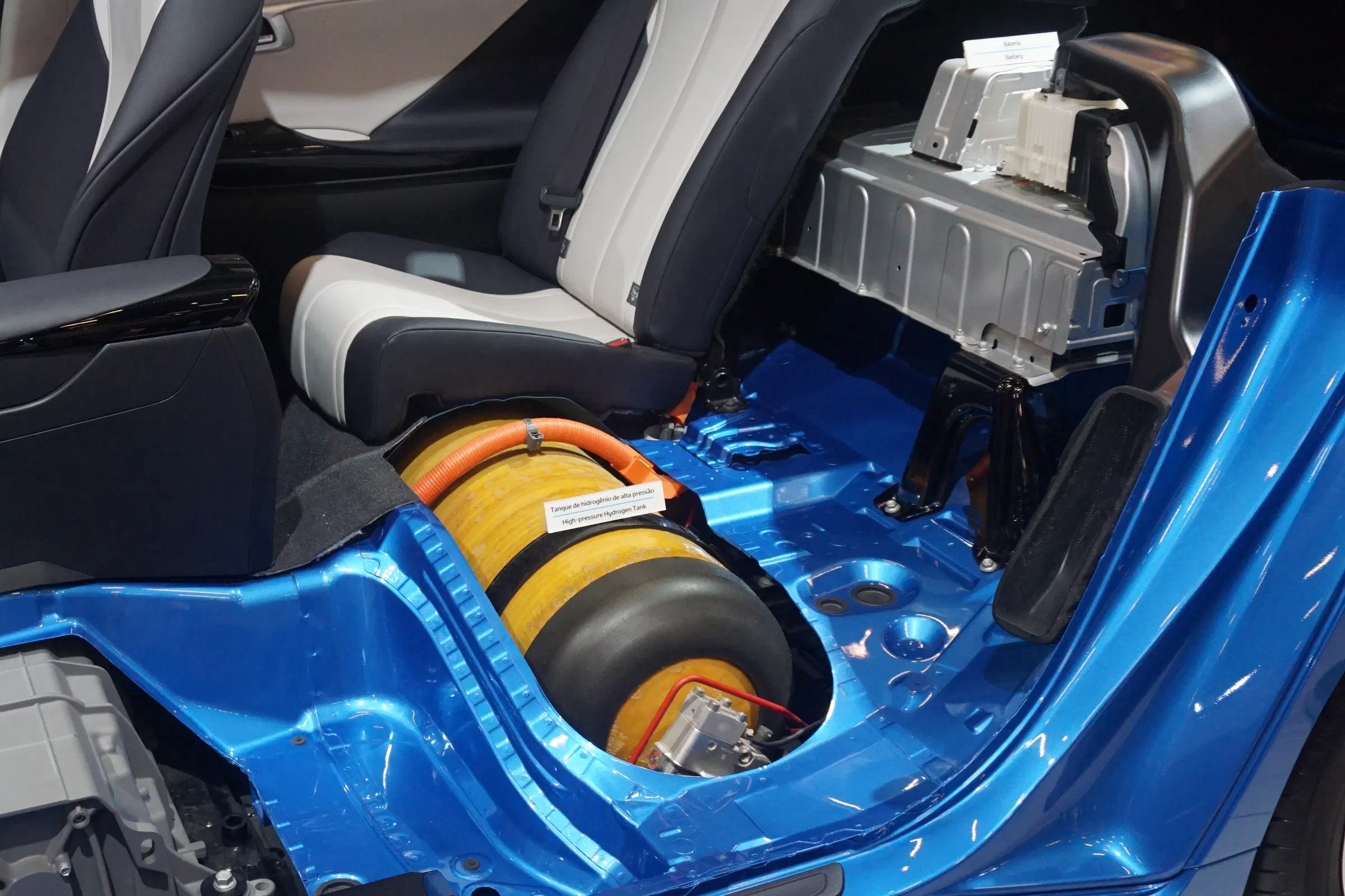
Credit Mario Roberto Durán Ortiz.
Green hydrogen is produced via electrolysis using electricity from renewable sources. State-of-the-art electrolysers achieve an efficiency of 83% based on the HHV and 70% based on the LHV (Martin, 2023). Since fuel cell efficiencies are usually quoted based on the LHV, to calculate the round-trip efficiency we must use the electrolyser’s efficiency based on the LHV. Further energy losses occur during compression of the hydrogen to 70 MPa. This requires approximately 15% of the energy contained in the hydrogen, and thus corresponds to an efficiency of 85%. Multiplying all these efficiencies, we obtain a round-trip efficiency of %.
4.5 Liquid hydrogen with fuel cell
For liquid hydrogen, the same assumptions hold as for compressed hydrogen, except that the weight of the tank is neglected. This is done because the primary purpose of a liquid hydrogen tank is to provide thermal insulation. Therefore, the weight of the tank scales approximately with the tank volume to the power of , and so the ratio of the tank weight to the fuel contents is a function of tank volume. Taking into account the motor and inverter efficiency of %, the specific propulsive energy is calculated as kWh/kg. While this would suggest a very low propulsion system mass, the tank mass can be expected to increase it considerably.
Hydrogen liquefies at -253°C or 20 K. Cooling hydrogen to this temperature is very energy intensive and requires cryogenic cooling machinery. Boil-off, which is caused not only by heat transfer but also by the exothermic conversion of orthohydrogen to parahydrogen, presents a significant challenge to the storage of liquid hydrogen.
To calculate the round-trip efficiency for liquid hydrogen, we must consider the energy required for liquefaction. This is around 35% of the energy contained in the hydrogen. Again taking into account the electrolyser efficiency of 70%, the round-trip efficiency is then calculated as %.
4.6 Uncompressed gaseous hydrogen with fuel cell
Uncompressed gaseous hydrogen could be carried in a hydrogen fuel ballonet, as shown in Fig. 15. For a passenger carrying airship, the lifting gas is likely to be Helium. Since hydrogen is lighter than helium, in the case of non-rigid airships the hydrogen ballonet needs to be positioned at the top of the hull. Ballast water must be carried and slowly dropped as fuel is consumed, to maintain constant static heaviness.[14][14]: In cold conditions, the ballast water must be prevented from freezing. Since over half of the hydrogen’s chemical energy is converted to waste heat in the fuel cell, this heat may be utilised to keep the ballast water warm, in addition to thermally insulating the ballast tank. This is because the reduction in hydrogen ballonet fill (gas bag fill in the case of a rigid airship) needs to be compensated by air ballonet fill (in case of a rigid airship, air enters the hull to occupy this volume), and air is heavier than hydrogen.[15][15]: Note that in the case of a non-rigid airship powered by uncompressed gaseous hydrogen the airship’s pressure altitude increases as fuel is consumed. This is because the reduction in hydrogen ballonet fill needs to be compensated by increased air ballonet fill, and more air ballonet fill brings with it a greater pressure altitude. At the beginning of the mission, when the hydrogen ballonet is full, we have (20)and at the end of the mission, when the ballonet is empty, we have (21)where is the volume of the full hydrogen fuel ballonet at pressure altitude, i.e. its maximum volumetric capacity. Dividing Eqn. 21 by Eqn. 20, we see that the air density at pressure altitude has decreased (and therefore the pressure altitude has increased): (22)The downside of this effect is that additional air ballonet fabric is required to allow the air ballonets to take up an additional volume of air equal to the capacity of the hydrogen fuel ballonet. The additional water ballast reduces the effective specific energy by a factor of = (according to Eqn. 9). However, as can be seen in Fig. 7, this still results in a greater specific propulsive energy than using compressed hydrogen. Note that in this analysis we neglect the weight of the fuel ballonet fabric needed to contain the uncompressed gaseous hydrogen, as this weight scales with the fuel volume to the power of , and therefore its proportion of the total mass decreases as the ballonet’s size increases. Therefore, compressed hydrogen is treated somewhat unfavourably in this analysis, as we are including its tank weight.
Nonetheless, we must also consider the other advantages of uncompressed gaseous hydrogen over compressed hydrogen, such as safety, ease of handling, and cost.
In a passenger-carrying airship, storing uncompressed gaseous hydrogen at the top of the airship, away from the passengers or crew, can surely be expected to be significantly safer than storing hydrogen at a pressure of 700 atmospheres in a tank close to the occupants. Another safety benefit of uncompressed gaseous hydrogen is the considerably control over buoyant lift it affords. In case of loss of buoyant lift due to a leak in the hull, buoyancy can be regained by prematurely releasing water ballast. Conversely, if heaviness needs to be increased, e.g. after an emergency landing following an all-engine failure to prevent the airship from floating away, this can be done by venting hydrogen fuel rather than much more expensive helium. Of course, both of these options are only available in the presence of unspent hydrogen fuel and water ballast.
In addition, as previously mentioned, in the case of passenger carrying airships, some of the reduction in buoyancy caused by hydrogen consumption could be compensated by the in-flight dropping of greywater, so that not all of the lifting gas’s buoyant lift is wasted — an option not available when using compressed hydrogen.
Furthermore, uncompressed gaseous hydrogen does not require multistage compressors or cryogenic cooling machinery, resulting in considerable capital and maintenance cost savings.
Lastly, uncompressed gaseous hydrogen also offers the best round-trip efficiency, and is therefore the cheapest hydrogen fuel option.[16][16]: It should be noted that we are neglecting the cost of the additional ballast water that needs to be carried when using uncompressed gaseous hydrogen. However, this cost can be assumed to be negligible compared to the cost of hydrogen fuel. The round-trip efficiency is the product of the electrolyser efficiency (70%) and the fuel cell efficiency and is %.
The uncompressed gaseous hydrogen could be generated on the airfield using electrolysers and renewable electricity, and stored in tethered balloons. This would permit electricity to be used at off-peak times such as during the night when it is available more cheaply, does not strain the grid, and enables load balancing. To refuel the airship, hydrogen would be pumped from the tethered balloons through the mast and into the airship’s hydrogen ballonet. This solution would thus not require any external hydrogen infrastructure, apart from what needs to be installed on the airfield itself.
Since the specific propulsive energy of gaseous hydrogen is lower than that of conventional fuels, it may provide insufficient range e.g. for ferry flying between continents. For such missions, a diesel tank and generator could be temporarily installed in the payload module, and the airship be powered using a combination of electricity from the hydrogen fuel cell and from the diesel generator. In this case, no ballast water would be taken. To calculate the specific propulsive energy of this combination, we assume the thermodynamic efficiency of the diesel generator to be equal to that of the RED A03 aircraft diesel engine. The electrical efficiency of the generator is assumed to be %. The specific propulsive energy of this combination of energy carriers is calculated using Eqn. 13 as kWh/kg, and the carbon dioxide emissions are kg /kWh shaft work, calculated using Eqn. 15. This combination of energy carriers is also shown in Fig. 7.
4.7 Batteries
Few battery-electric aircraft have been built to date, and even fewer are certified. One of them is the Pipistrel Velis Electro, an electric trainer. Its Li-ion batteries weigh 70 kg and have a capacity of 11 kWh each (E-Flight Academy, 2022). While it is not clear if this includes the weight of all the associated cooling equipment, necessary structural mounts, and thermal runaway mitigations, for the purposes of this analysis we shall assume that this is the system-level weight. Based on these numbers, current aviation batteries can be assumed to have a system-level specific energy of around 0.16 kWh/kg, significantly lower than any of the other energy carriers described here. The battery discharge efficiency is assumed to be %, which corresponds to a discharge rate of around 1C and a discharge depth of 80% (Redondo-Iglesias & Pelissier, 2022). Together with an electric motor and inverter efficiency of %, this results in a specific propulsive energy of kWh/kg.
Assuming a charge efficiency of 97% (when fast-charging at 3C and with a depth of discharge of 90%, as per Redondo-Iglesias & Pelissier (2022)), we obtain a round-trip efficiency of %.
5 Conclusions
According to Fig. 5, gaseous fuels with a density similar to that of air offer higher specific propulsive energies than liquid or compressed fuels in airship applications, due to their displacement of lifting gas. This means that the effective propulsive energy of a gaseous fuel is greater than that of a liquid or compressed fuel, even if both fuels have the same gravimetric energy density.
Uncompressed gaseous hydrogen, carried in a fuel ballonet or fuel gas bag, offers unique advantages over other renewable energy carriers. It has a comparatively high specific propulsive energy (among its renewable contenders), requires no multistage compressors or cryogenic cooling equipment thereby making it cheaper, needs no exhaust water recovery to maintain static heaviness, requires no external hydrogen infrastructure other than what would need to be installed on the airfield, and has the highest round-trip efficiency, making it also the most efficient hydrogen option. While the round-trip efficiency of batteries is more than twice as high, batteries have almost 10 times lower specific propulsive energy. In addition, in cold conditions the waste heat produced by oxidising hydrogen may be used to heat the cabin, which can’t be done with a battery since it produces much less heat.
There appear to be few reasons to use compressed hydrogen as an airship fuel as opposed to uncompressed gaseous hydrogen. For the same available propulsive energy, uncompressed gaseous hydrogen is not only lighter on a system level, but also significantly safer and cheaper.
Biogas is suggested as a possible renewable airship fuel, and may be preferred in regions where renewable electricity is not readily available, but feedstock for biogas production is. However, where renewable electricity is readily available, uncompressed gaseous hydrogen is likely a better choice, leaving the carbon dioxide contained in biogas available for carbon capture or the production of biofuels.
Renewable energy solutions, with the exception of liquid hydrogen, have lower specific propulsive energies than fossil fuel solutions, placing even greater emphasis on minimising drag and maximising efficiency in general.
While liquid hydrogen has the potential for the highest specific propulsive energy, it is also likely uneconomic due to the considerable additional energy input and cryogenic machinery required by liquefaction, in addition to other challenges such as boil-off.
Batteries currently have significantly lower specific propulsive energy than other renewable energy carriers.